
- Home
-
News
-
Outdoor Living
-
How Tall Should a Pergola Be?
How Tall Should a Pergola Be?
A dining terrace and a small garden lounge may need different pergola heights, even if they cover a similar area. Start with how you want to use the space, then refine your choice by accounting for the roof, nearby building features, and the dimensions your supplier provides.
Start with the activity that determines the layout
Draw the furniture arrangement before choosing a height. For dining, show the table with chairs pulled out and identify where people will walk behind them. For a lounge, mark the seating positions and the view across the garden. If the pergola will cover both, decide whether they share one open area or occupy distinct zones. That choice determines where you need to assess the space while standing and where the seated experience matters most.
Use these activity ranges to compare an initial roof-frame position:
|
Planned use |
Roof-frame height to consider |
|
Outdoor dining |
About 9–10 ft / 2.7–3.0 m |
|
Compact garden lounge |
About 8–9 ft / 2.4–2.7 m |
|
Terrace beside the house |
About 9–10 ft / 2.7–3.0 m |
|
Larger entertaining area |
About 9–11 ft / 2.7–3.4 m |
Mitchell Construction's height guide provides the dining, patio, garden and entertainment ranges used here; the garden range is applied to the compact lounge. Its measurement runs from the ground to the top of the horizontal roof beams or rafters. Metric values are rounded to one decimal place.
For a mixed dining and lounge layout, begin with the dining range and assess the seated view within it. Moving towards the upper end should answer a specific preference, such as wanting a more open visual relationship between the two zones. If the lower end already produces the proportions you prefer, there is no need to increase the height simply because the footprint includes more than one activity.
Mark any intended pendant light above its actual position on the plan. A fitting over the center of a table and one over the walking route affect different parts of the layout. With those locations established, you can translate the initial roof-frame choice into the space available below it.
Compare what remains beneath the complete roof
A product drawing may give an overall height that includes components above the main frame. Clear height is a different measurement: the distance from the patio surface to the lowest overhead element at the location being considered. Keep all three labels distinct when comparing a supplier's drawing with your initial range. To compare overall height with the activity ranges, subtract any extension above the beam or rafter tops. The remaining dimension is the roof-frame height.
Consider two layouts with the same overall height. Their overhead assemblies occupy different amounts of vertical space:
|
Illustrative measurement |
Layout A |
Layout B |
|
Overall height above the patio |
2.70 m |
2.70 m |
|
Distance from the highest point to the lowest overhead obstruction |
0.20 m |
0.35 m |
|
Resulting clear height |
2.50 m, about 8 ft 2 in |
2.35 m, about 7 ft 9 in |
Subtracting the second row from the first gives the third. Layout A leaves 150 mm more clear space, despite the matching external height. The inch equivalents are rounded using NIST's length conversion factors.
Suppose you prefer the first layout's headroom but are considering the second roof assembly. Retaining that preference would require an overall height of 2.85 m: the desired 2.50 m plus the assembly's 0.35 m. You now have a concrete choice to investigate—whether the taller external profile fits the site, or whether another roof arrangement better suits the available space.
For a hanging fitting, identify whether its bottom edge is already included in the obstruction measurement. If it sits lower, use that point for the clearance calculation at its location. This avoids counting the same drop twice or overlooking it entirely. Where the fitting is above the table, assess the separate walking route beneath the roof frame as well. The layout can therefore contain more than one relevant clear-height dimension.
Find out whether the preferred profile fits beside the house
For the taller option in the example, the next question is where its top edge would sit relative to the building. Draw a side view through the proposed pergola and the adjacent wall. Use the patio surface as the common starting level, then add the underside of the eaves, gutter projections, and the tops of nearby openings. Include the horizontal distance between those features and the proposed roof; matching heights alone do not show whether two parts occupy the same space.
Now include movement. Show an outward-opening window or shutter open, and identify the moving envelope of the proposed louver roof on the supplier's drawing. A profile that fits when everything is closed may require a different position when either element moves. Record the particular conflict, such as an opening crossing the roof area, rather than requesting an unspecified increase in clearance.
If the preferred external height conflicts with the eaves, return to the choice established by the calculation. A shallower roof assembly could retain the desired headroom within a lower profile; moving the pergola away from the wall could change its relationship to the overhang. Assess each proposed alternative against the furniture plan before accepting it, because moving the structure also moves the covered area and posts.
A freestanding pergola away from the building requires a different comparison. Sketch its outline against the terrace width and nearby structures, then view that outline from the main seating position inside the home. Identify the view you want to preserve and where the front beam would appear within it. This gives a specific reason to adjust the profile instead of relying on the height figure alone.
Keep the ground reference consistent across these views. Where the patio has steps or a slope, identify the intended post positions and record their level differences from one labeled point. If a new surface is planned, include its proposed finished level on the same sketch so the height discussion uses the surface you will actually stand on.
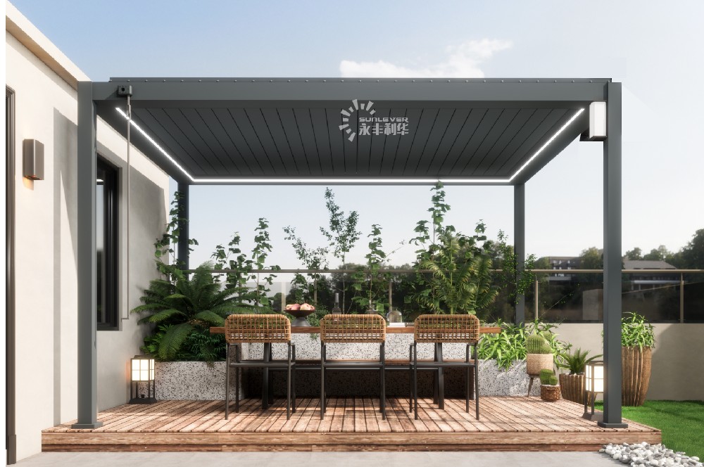
Give SUNLEVER the dimensions that resolve the choice
SUNLEVER offers standard-size and custom pergolas. Compare a standard option with the plan and side view you have developed. Check the footprint, post positions, and relevant vertical dimensions together.
For a custom inquiry, separate what the site fixes from what you would like to achieve. The measured position of an existing eave is a fixed input; a preferred sense of openness is a design preference. State which requirements you are willing to adjust. In the worked example, retaining the chosen headroom would be one priority, while the roof assembly and external profile would be the items to discuss.
Send the available length and width, the preferred post locations, and the annotated height views. Add the country and city, the surface type, and whether you want the pergola freestanding or connected to the building. Label dimensions in one unit system and identify both endpoints of each measurement. A photograph with the same labels helps connect the drawing to the actual setting, especially when a projection is hard to represent in a simple sketch.
Include planned side features in that package. For screens, curtains, or glass doors, identify the relevant side and the opening you want to use; for overhead fittings, provide their intended positions and dimensions, if available. This lets those elements be considered with the selected profile before a configuration is settled.
Send the site package to SUNLEVER with the unresolved choice stated clearly. For example, ask which standard or custom arrangement can preserve your preferred headroom within the measured building constraints.